IoT Home Automation System ESP32 /Nodemcu
Creating an IoT-based Home Automation System with Arduino involves controlling various home appliances, such as lights and fans, over the internet using a Wi-Fi module like ESP8266 or ESP32. In this example, we'll use ESP8266 to control an LED (representing a light) from a mobile app or a web interface.
Components:
- ESP8266 (NodeMCU) or ESP32
- Relay Module (to control appliances)
- LED (for testing purposes instead of real appliances)
- Resistors
- Jumper Wires
- Breadboard
- Smartphone or Computer (to send commands through a web interface)
Basic Concept:
The ESP8266 will connect to your Wi-Fi network and serve a simple web interface where you can control devices like lights, fans, etc. You can use a browser or mobile app (through the web interface) to turn on/off these devices.
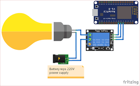
Circuit Diagram:
- D1 (GPIO5) controls the relay to turn on/off the appliance.
- Use 5V or 220V power (depending on the appliance) to drive the relay and the appliance.
Arduino Code for ESP8266:
This code creates a simple web server that allows you to control an LED or a relay using a browser.
#include <ESP8266WiFi.h>
#include <ESP8266WebServer.h>
// Replace these with your network credentials
const char* ssid = "your_SSID";
const char* password = "your_PASSWORD";
// Set the GPIO pin for the relay (or LED)
const int relayPin = D1;
// Create an instance of the server
ESP8266WebServer server(80); // Web server running on port 80
void setup() {
// Start the serial communication
Serial.begin(115200);
delay(10);
// Connect to Wi-Fi
WiFi.begin(ssid, password);
while (WiFi.status() != WL_CONNECTED) {
delay(1000);
Serial.println("Connecting to WiFi...");
}
Serial.println("Connected to WiFi");
Serial.print("IP Address: ");
Serial.println(WiFi.localIP());
// Set the relay pin as an output
pinMode(relayPin, OUTPUT);
digitalWrite(relayPin, LOW); // Initially turn off the appliance
// Define routes
server.on("/", HTTP_GET, handleRoot);
server.on("/turn_on", HTTP_GET, handleTurnOn);
server.on("/turn_off", HTTP_GET, handleTurnOff);
// Start the server
server.begin();
Serial.println("Web server started");
}
void loop() {
// Handle client requests
server.handleClient();
}
void handleRoot() {
String html = "<html><body>";
html += "<h1>ESP8266 Home Automation</h1>";
html += "<p><a href=\"/turn_on\"><button>Turn On</button></a></p>";
html += "<p><a href=\"/turn_off\"><button>Turn Off</button></a></p>";
html += "</body></html>";
server.send(200, "text/html", html);
}
void handleTurnOn() {
digitalWrite(relayPin, HIGH); // Turn on the appliance
server.send(200, "text/html", "<h1>Appliance is ON</h1><p><a href='/'>Back</a></p>");
}
void handleTurnOff() {
digitalWrite(relayPin, LOW); // Turn off the appliance
server.send(200, "text/html", "<h1>Appliance is OFF</h1><p><a href='/'>Back</a></p>");
}
Testing and Accessing:
- Upload the code to the ESP8266 using the Arduino IDE.
- Open the Serial Monitor to see the assigned IP address once the ESP8266 connects to Wi-Fi.
- Open a browser and type the IP address of the ESP8266 (e.g.,
http://192.168.1.x). - You should see a page with buttons "Turn On" and "Turn Off".
- Click the buttons to control the relay and simulate turning appliances on/off.


0 Comments